Mr. Patchbay
No Normals
No Normals is when the top-row of jacks is not connected to the bottom-row of jacks.
Full Normals / Normals Strapped
Full-Normal : Each jack on the top-row is connected to the jack under it on the bottom-row. This allows the audio or video signal to “pass-through” the patchbay without using a patch cable. When we want to change the “normal” signal path we can use a patch cable to change the destination of the signal.
Placing a patch cable into the either row breaks the signal path. The signal follows the patch cable to where it is patched.
Half Normal
Half-Normal: Each jack on the top-row is connected to the jack under it on the bottom-row. This allows the audio or video signal to “pass-through” the patchbay without using a patch cable. When we want to change the “normal” signal path we can use a patch cable to change the destination of the signal.
Placing a patch cable into the bottom-row breaks the signal path. Placing a patch cable into the top-row allows the signal to still go to the jack under it on the bottom-row (without breaking the normal) and also follows the patch cable.
How to Set the Normals for ADC Punch Down Patchbays
48 Point Patchbays:
To make Full Normal wire from Blue #1 to Blue #25
From Orange #1 to Orange #25; wire from Blue #2 to Blue #26 From Orange #2 to Orange #26 etc.
To make Half Normal wire from Red #1 to Blue #25
From Black #1 to Orange #25; wire from Red #2 to Blue #26 From Black #2 to Orange #26 etc.
96 Point Patchbays:
To make Full Normal wire from Blue #1 to Blue #49 ; wire from Blue #2 to Blue #50
From Orange #1 to Orange #49; From Orange #2 to Orange #50 etc.
To make Half Normal wire from Red #1 to Blue #49
From Black #1 to Orange #49; wire from Red #2 to Blue #50 From Black #2 to Orange #50 etc.
Please see the above instructions in action as a Quicktime movie on the “How to Wire a Patchbay” page.
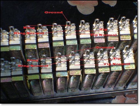
How to Set Normals for Solder-Type Patchbay
For the solder-type patchbays such as the ADC PJ-739 and many others the normaling jacks are lay out like shown below: