I do have a question for you though, am I able to wire a single patchbay both half normaled and thru? (Say the first half patch points are half normaled and the second half are not). Is one patchbay capable of all 3 types of connections? Just depending on how you wire it? Because I see switchcraft has 3 different models, one for each type of connection.
Thanks so much for your time,
Matt
Sent from my T-Mobile 4G LTE Device
Hey Matt,
Yes each jack can be wired no-normal or half-normal or full normal. The three different model SwitchCraft patchbays is just marketing.
On Sep 2, 2016, at 10:54 PM, Matt ****** wrote: Hi Bob,
Thanks so much for the speedy response, I really appreciate it. I saw that picture on your site and just wasn't sure how the connection for full normal would be different from half normal.
Thank you again for the information and quick response - I love that! I will be placing the order now!
Matt
Sent from my T-Mobile 4G LTE Device
Hey Matt,
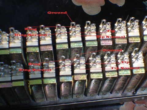
Thank you for the order. If you are using Phantom Powered mics on one or more of the patchbays you will need to set those channels to bussed grounds or grounds vertically strapped. For bussed grounds you will solder a wire across the grounds of those channels and attach that ground to anything that is grounded. GVS is top-row to bottom-row and you just connect the ground eyelet from the top-row to the ground solder eyelet on the bottom-row for each set of channels. The full normal has both top-row & bottom-row tied together via the normal solder eyelets on each channel letting the signal pass through the two patchbay rows in “normal” fashion. Inserting a patch cable into either row breaks the connection an the signal follows the patch cable. The half normal has both top-row & bottom-row tied together via the normal solder eyelets on each channel letting the signal pass through the two patchbay rows in “normal” fashion. Inserting a patch cable into the bottom-row breaks the connection an the signal follows the patch cable. Inserting a patch cable into the top-row does not break the connection. The signal splits when you insert a patch cable into the top-row allowing all kinds of fun things to do with your audio signal.